Optical Coherence Tomography (OCT) is a non-invasive imaging device that uses near-infrared light interference to obtain cross-sectional images of the fundus and anterior segment of the eye. Axial resolution in commercial devices is generally 5–10 µm (2–3 µm in ultra-high-resolution research devices), which is more than an order of magnitude higher than ophthalmic B-mode ultrasound (approx. 150 µm). This resolution enables evaluation of the fine structures of the retina and optic nerve, aiding in the diagnosis and monitoring of various eye diseases.
After Huang et al. reported cross-sectional imaging of biological tissues using OCT in 1991, it became widely adopted in ophthalmology. 11) Today, it is used in a wide range of fields including retinal diseases, glaucoma, anterior segment diseases, and neuro-ophthalmology.
There are three main generations of OCT. The characteristics of each are shown below.
TD-OCT (1st generation)
This first-generation method acquires cross-sectional images by changing the optical path length with a movable reference mirror. With a central wavelength of around 800 nm, A-scan speed of several hundred scans/sec, and axial resolution of about 10 µm, it has now been largely replaced by SD-OCT due to speed constraints.
SD-OCT (2nd generation)
This method uses a spectrometer and Fourier transform to acquire depth information simultaneously. With a central wavelength of around 840 nm, A-scan speed of roughly 25,000 to 85,000 scans/sec, and axial resolution of 5 to 7 µm, it is widely used for precise evaluation of the macula and optic nerve head.
SS-OCT (3rd generation)
This method uses a wavelength-swept laser. Central wavelength is 1050–1060 nm, and A-scan speed is 100,000 to 400,000 scans/sec. Due to high penetration at longer wavelengths and small sensitivity roll-off, a general advantage is the ability to visualize the entire choroid without using EDI mode. It is also suitable for high-speed, wide-area imaging. Values vary depending on the device model.
EDI-OCT (Enhanced Depth Imaging OCT): An imaging mode that visualizes the choroid in detail by setting the zero-delay line to the choroidal side. It can also be used with SD-OCT.
OCTA (OCT angiography): Extracts blood flow signals from repeated scans of the same area to noninvasively visualize vascular structures. While it does not use contrast agents, it cannot directly evaluate fluorescein leakage and is used complementarily with contrast imaging such as FA. 12)
Nomenclature standardization: The former “IS-OS layer” has been renamed the ellipsoid zone (EZ), and the junction between the outer segments and the RPE is now called the interdigitation zone (IZ) (IN-OCT nomenclature) 16).
QIs OCT a painful test?
A
OCT is a noninvasive, non-contact test that is completely painless. Although dilating eye drops may be needed, it only involves shining light and does not touch the cornea or retina. The test usually takes only a few minutes.
Retinal thickness map; used for treatment response assessment in diabetic macular edema and RVO
Glaucoma analysis (cpRNFL/GCA)
RNFL thickness, GCL+IPL thickness. Glaucoma diagnosis and progression assessment
The observation sites are broadly divided into posterior segment OCT (macular area, peripapillary area, peripheral area) and anterior segment OCT (AS-OCT; cornea, anterior chamber, angle).
Have the patient fixate on the fixation light and align the device toward the pupil.
Start with a cross scan passing through the fovea.
Add a scan mode appropriate for the disease.
For patients with poor fixation, use an external fixation light or have an assistant help with fixation.
Pupil dilation is generally unnecessary, but perform under dilation for moderate or greater cataract or small pupil.
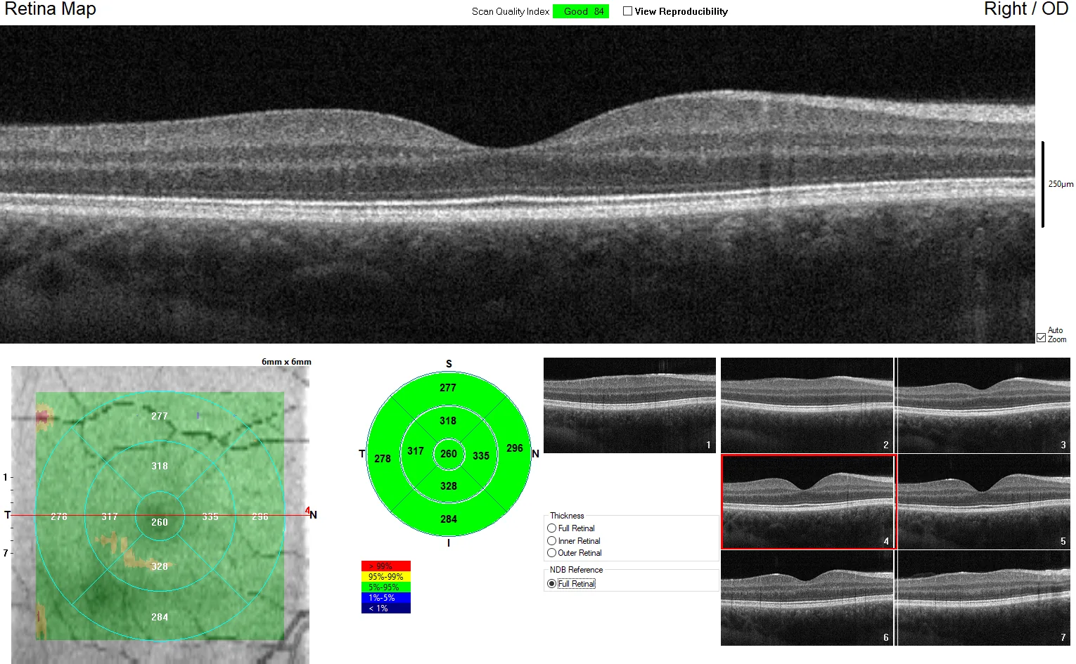
In foveal scans, it is important to visualize slices where the foveal pit is present and the inner retinal layers are absent. In macular diseases, the center may shift due to poor fixation; understanding the normal retinal structure improves examination and diagnostic skills.
3. Indications and findings in retinal and macular diseases
Cross-sectional image (horizontal section) of a healthy macula in a 24-year-old male captured by SD-OCT, showing the foveal pit and normal reflective bands and boundaries from the vitreous to the retina and choroid.
In a foveal scan, the following tissues, boundaries, and reflective bands are identified from inner to outer layers16).
This list includes the vitreous and choroid outside the retina, as well as boundaries and reflective bands that are not histological layers, so it does not imply “13 retinal layers.” Evaluating the reflectivity and continuity of each landmark is fundamental to interpretation16).
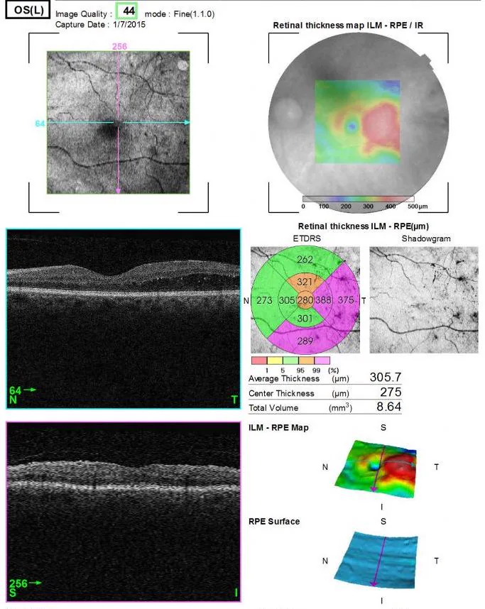
OCT image of diabetic macular edema (DME) in the left eye of a 61-year-old patient with type 2 diabetes, confirming macular retinal thickening and cystoid spaces. This corresponds to the representative OCT findings of diabetic macular edema discussed in the section “Indications and Findings in Retinal and Macular Diseases.”
Macular hole is visualized as a full-thickness defect of the retina. SD-OCT is the most sensitive and specific test for diagnosing macular holes1).
Epiretinal membrane (ERM) is recognized as a hyperreflective layer on the internal limiting membrane2). Regarding postoperative visual acuity, 80% of cases are reported to achieve a visual improvement of 2 lines or more after vitrectomy2).
Diabetic macular edema: Quantitative measurement of retinal thickness by OCT serves as an indicator for initiating and retreating anti-VEGF therapy3). DRIL (Disorganization of Retinal Inner Layers) not only correlates with visual acuity, but changes in its extent have been reported to predict subsequent visual acuity changes, positioning it as an OCT biomarker reflecting visual prognosis and treatment response.13)
RVO: OCT enables quantitative assessment of macular edema and detection of vitreoretinal interface changes4).
AMD: RPE detachments are classified into serous, fibrovascular, and drusenoid pigment epithelial detachments, and CNVM can be classified into type 1 (sub-RPE), type 2 (supra-RPE), and type 3 (intraretinal neovascularization)5).
Interpretation of hyperreflective and hyporeflective patterns
Punctate hyperreflectivity. Those thought to reflect microglial cells feature a maximum diameter of less than 30 µm, intermediate reflectivity comparable to the nerve fiber layer, and no posterior shadowing
PAMM (paracentral acute middle maculopathy): In the acute phase, it appears as a band-like hyperreflectivity near the OPL/INL, and may later leave INL thinning. 14)
Mirror artifact: Due to incorrect scan range settings, the actual image is inverted and displayed overlapping.
Vignetting: Signal attenuation in the periphery, depending on the incident angle of the illumination light.
Out-of-range error: Structures outside the set depth range are folded back and displayed.
Patient Factors
Blink artifact: Horizontal gaps occur due to blinking during scanning.
Eye movement: Poor fixation causes image misalignment or distortion.
Position shift: Caused by head movement during scanning.
Software Factors
Segmentation error: The automatic layer segmentation algorithm misidentifies retinal layers. This occurs frequently in lesions, severe cataracts, or high myopia.
Manual correction or rescanning is used to address this. Quality index names and thresholds vary by device, so check the device’s standards and original images.
QAre there any diseases that OCT cannot detect?
A
OCT has excellent diagnostic accuracy for diseases of the macula and posterior pole, but it is not suitable for detecting peripheral retinal lesions (such as lattice degeneration and retinal tears). In addition, image quality decreases when cataracts or vitreous opacities are severe, reducing diagnostic reliability. Wide-angle fundus photography and indirect ophthalmoscopy are used for peripheral lesions.
SD-OCT is a non-contact, non-invasive imaging technique that objectively evaluates structural damage in glaucoma, and its high utility in glaucoma diagnosis is well recognized 6). It is particularly useful in diagnosing preperimetric glaucoma, as it can detect structural changes before the onset of visual field defects 6)7).
Measurement principle: Quantifies the thickness between the internal limiting membrane (ILM) and the RNFL boundary
TSNIT map: Displays the RNFL thickness on a circle around the optic disc specified by the device, in the order T (temporal) → S (superior) → N (nasal) → I (inferior) → T (temporal)
Normal pattern: Shows a bimodal peak in the superior and inferior directions (reflecting the anatomical distribution of arcuate nerve fiber bundles) 6)
Interpretation: Comparison with a normal database is useful, but axial length, optic disc shape, and segmentation should be checked, and judgment should be made in conjunction with visual field testing. 6)7)
ONH Parameters
Optic disc analysis: Automatically delineates the optic disc, cup, and rim
Bruch’s membrane reference: Defines the disc margin at the Bruch’s membrane opening and calculates the shortest distance to the ILM
High diagnostic performance indicators: Vertical rim thickness, rim area, and vertical cup-to-disc ratio have the highest diagnostic ability 7)
BMO-MRW: Rim width evaluation based on the Bruch’s membrane opening, with excellent reproducibility 6)
Ganglion Cell Analysis (GCA)
Measurement target: Combined thickness of the ganglion cell layer (GCL) and inner plexiform layer (IPL) around the macula
Comparison with the normative database is useful, but attention must be paid to false positives and false negatives due to the following factors.
High myopia: Temporal shift of the RNFL bundle may cause normal eyes to be judged as “thinned.” The longer the axial length, the thinner the RNFL tends to be measured6)
Media opacities: Conditions such as cataracts reduce signal strength, potentially leading to underestimation of RNFL thickness
Segmentation errors: More likely to occur in cases of tilted optic disc, scleral staphyloma, peripapillary atrophy, or epiretinal membrane
Eye movements and blinking: Can be mitigated by eye-tracking functionality
Two approaches are used to determine glaucoma progression: event analysis and trend analysis.
Event analysis: Progression is determined when follow-up measurements exceed a threshold from baseline.
Trend analysis: Progression is determined by calculating the rate of change over time (μm/year) using regression analysis.
cpRNFL also thins physiologically with aging, at a rate generally reported in longitudinal studies as approximately 0.2 to 0.5 µm/year. When determining progression, confirm whether the rate of change exceeds this age-related change, not only a single difference but also whether the change is reproducible under the same device and imaging conditions, and whether there are segmentation errors. Interpret the device’s progression analysis together with visual field tests and clinical findings. 6)7)
In advanced glaucoma, because of residual glial and fibrous tissue, RNFL thickness does not decrease below approximately 50 µm, making it difficult to detect progression due to the “floor effect.” Use visual field tests together and also evaluate macular ganglion cell-related parameters. 6)7)
QHow should SD-OCT evaluation be performed in highly myopic eyes?
A
In highly myopic eyes, comparison with the normal database has limitations. Because the RNFL bundle shifts temporally, it may be judged as “thinning” even in normal eyes. In such cases, perform longitudinal comparisons using the same device with each patient as their own baseline, and evaluate together with the original images, segmentation, and visual field tests. 6)7)
OCT is rapidly expanding in the field of neuro-ophthalmology 9). Peripapillary RNFL (cpRNFL) thickness and macular GCIPL (ganglion cell layer + inner plexiform layer) are key evaluation parameters, and changes may be detected before the onset of obvious clinical signs or visual dysfunction 9).
Optic neuritis / multiple sclerosis (MS): RNFL and GCIPL thinning are important imaging findings. Thinning may also be observed in MS patients without ocular symptoms, and its association with visual function and central nervous system lesions is being studied. 9)
NMOSD is characterized by severe optic atrophy, and the frequency of microcystic macular edema is significantly higher (approximately 40% in AQP4-positive cases) than in MS (5%) 9). In MOG-IgG-associated optic neuritis, GCIPL is relatively preserved, whereas in AQP4-IgG-associated optic neuritis, it is markedly lost 9).
Optic disc drusen (ODD) detection: EDI-OCT is the gold standard 9). ODD appear as hyporeflective structures with hyperreflective margins located above the lamina cribrosa, and EDI-OCT has better detection ability for buried drusen than B-scan ultrasound, autofluorescence, or CT. PHOMS (peripapillary hyperreflective ovoid mass-like structures) should be distinguished from ODD as a separate phenomenon 9).
Compressive optic neuropathy: Preoperative cpRNFL thickness (and macular GCIPL thickness) has been reported in multiple studies as a predictive factor for postoperative visual function recovery. In a meta-analysis of 4 studies, 202 cases, and 395 eyes targeting optic chiasm compression, the group with normal preoperative RNFL showed better recovery than the thinned group (pooled odds ratio 15.61, 95% confidence interval 4.09 to 59.61). In a study of suprasellar tumors, preoperative RNFL thickness ≥70 μm was associated with postoperative improvement in visual acuity and visual field 9). However, specific thresholds vary across studies, and recovery is possible even with thinned RNFL, so decisions should be made in conjunction with age, disease duration, tumor size, etc.
Because segmentation algorithms and normative databases differ between devices, direct comparison of measurements across devices requires caution. For longitudinal evaluation, it is desirable to use the same device and imaging conditions 17).
OCT utilizes low-coherence interferometry. The reflection intensity at each depth is calculated from the reflected light of the measurement beam and the reference beam, and A-scans in the depth direction are arranged laterally to form B-scans (tomographic images). 11)
TD-OCT (time-domain): A movable mirror on the reference arm is mechanically moved to sequentially change the optical path length, acquiring reflection intensity at each depth in sequence. Due to speed limitations, clinical use is now largely obsolete.
SD-OCT (Spectral Domain): The reference mirror is fixed, and the reflected light is separated by wavelength using a spectrometer such as a diffraction grating. By applying Fourier transform to the obtained spectrum, information from all depths is acquired simultaneously. Imaging speed is dramatically improved, and noise is reduced.
SS-OCT (Swept Source): Tomographic images are constructed using the spectrum obtained from a light source that rapidly sweeps wavelengths. Generally, it has advantages for imaging deep structures and wide areas, but performance varies by device.
OCTA: Repeated imaging of the same area extracts changes as blood flow signals, displaying retinal and choroidal vessels by depth. Be aware of artifacts such as segmentation and projection. 12)
In glaucoma and optic nerve diseases, the following three layers are preferentially evaluated 9).
RNFL (Retinal Nerve Fiber Layer): Contains the axons of retinal ganglion cells (RGCs)
GCL (Ganglion Cell Layer): Contains the cell bodies of RGCs
IPL (Inner Plexiform Layer): Contains synapses between RGC dendrites and bipolar cell axons
With RGC damage, the RNFL and macular ganglion cell-related layers become thinner. SD-OCT evaluates RGC axons via RNFL thickness and the inner layers including cell bodies via GCA. Interpret not only by comparison with a normal database but also by combining longitudinal changes and visual field findings. 6)7)
QWhat is the difference between SD-OCT and SS-OCT?
A
SD-OCT uses a spectrum acquired by a spectrometer, while SS-OCT uses a spectrum from a light source that sweeps wavelengths to construct tomographic images. SS-OCT generally has advantages for deep and wide-area imaging, but wavelength, speed, and resolution vary by device. Which is suitable depends on the imaging target and device performance.
Longitudinal studies are needed to establish the utility of OCT as a screening and monitoring tool for neurodegenerative diseases such as Alzheimer’s disease and Parkinson’s disease 9). RNFL and GCIPL thinning in patients with REM sleep behavior disorder (RBD) is attracting attention as a surrogate marker for prodromal Parkinson’s disease 9).
Evaluation of ocular complications of systemic diseases through OCT findings is also a growing area of research.
Dou et al. (2024) reported a case of a patient with membranous nephropathy who developed a giant RPE tear, and documented the lesion course using OCT. This is a single case report and does not demonstrate a causal relationship between membranous nephropathy and RPE tears, nor the effectiveness of OCT screening for systemic diseases in general. 10)
Inter-device standardization: Because segmentation methods and normative databases differ between devices, standardizing longitudinal comparisons across devices remains a challenge. 17)
MS diagnostic criteria: In the 2024 revised McDonald criteria, the optic nerve was added as a fifth anatomical site. OCT is positioned as a supplementary test for optic nerve lesions alongside visual evoked potentials and orbital MRI. 15)
Flaxel CJ, Adelman RA, Bailey ST, Fawzi A, Lim JI, Vemulakonda GA, et al. Idiopathic Macular Hole Preferred Practice Pattern®. Ophthalmology. 2020;127(2):P184-P222. doi:10.1016/j.ophtha.2019.09.026. PMID:31757499.
Flaxel CJ, Adelman RA, Bailey ST, Fawzi A, Lim JI, Vemulakonda GA, et al. Idiopathic Epiretinal Membrane and Vitreomacular Traction Preferred Practice Pattern®. Ophthalmology. 2020;127(2):P145-P183. doi:10.1016/j.ophtha.2019.09.022. PMID:31757497.
Lim JI, Kim SJ, Bailey ST, et al. Diabetic Retinopathy Preferred Practice Pattern. Ophthalmology. 2025 Apr;132(4):P75-P162. doi:10.1016/j.ophtha.2024.12.020. PMID:39918521.
Kovach JL, Bailey ST, Kim SJ, Lim JI, Vemulakonda GA, Ying GS, et al. Retinal Vein Occlusions Preferred Practice Pattern®. Ophthalmology. 2025;132(4):P303-P343. doi:10.1016/j.ophtha.2024.12.025. PMID:39918523.
Vemulakonda GA, Bailey ST, Kim SJ, Kovach JL, Lim JI, Ying GS, et al. Age-Related Macular Degeneration Preferred Practice Pattern®. Ophthalmology. 2025;132(4):P1-P74. doi:10.1016/j.ophtha.2024.12.018. PMID:39918524.
Gedde SJ, Vinod K, Wright MM, et al. Primary Open-Angle Glaucoma Preferred Practice Pattern. Ophthalmology. 2021 Jan;128(1):P71-P150. doi:10.1016/j.ophtha.2020.10.022. PMID:34933745.
Gedde SJ, Lind JT, Wright MM, Chen PP, Muir KW, Vinod K, Li T, Mansberger SL; American Academy of Ophthalmology Preferred Practice Pattern Glaucoma Panel. Primary Open-Angle Glaucoma Suspect Preferred Practice Pattern. Ophthalmology. 2021 Jan;128(1):P151-P192. doi:10.1016/j.ophtha.2020.10.023. PMID:34933743.
Lo C, Vuong LN, Micieli JA. Recent advances and future directions on the use of optical coherence tomography in neuro-ophthalmology. Taiwan journal of ophthalmology. 2021;11(1):3-15. doi:10.4103/tjo.tjo_76_20. PMID:33767951; PMCID:PMC7971436.
Dou R, Chu Y, Han Q, Zhang W, Bi X. Giant retinal pigment epithelium tears with membranous nephropathy: a case report and literature review. BMC ophthalmology. 2024;24(1):177. doi:10.1186/s12886-024-03426-5. PMID:38632537; PMCID:PMC11025203.
Huang D, Swanson EA, Lin CP, et al. Optical coherence tomography. Science. 1991;254(5035):1178-1181. doi:10.1126/science.1957169. PMID:1957169; PMCID:PMC4638169.
Sun JK, Lin MM, Lammer J, et al. Disorganization of the retinal inner layers as a predictor of visual acuity in eyes with center-involved diabetic macular edema. JAMA Ophthalmol. 2014;132(11):1309-1316. doi:10.1001/jamaophthalmol.2014.2350. PMID:25058813.
Montalban X, Lebrun-Frénay C, Oh J, et al. Diagnosis of multiple sclerosis: 2024 revisions of the McDonald criteria. Lancet Neurol. 2025;24(10):850-865. doi:10.1016/S1474-4422(25)00270-4. PMID:40975101.
Staurenghi G, Sadda S, Chakravarthy U, Spaide RF; International Nomenclature for Optical Coherence Tomography (IN-OCT) Panel. Proposed lexicon for anatomic landmarks in normal posterior segment spectral-domain optical coherence tomography: the IN-OCT consensus. Ophthalmology. 2014;121(8):1572-1578. doi:10.1016/j.ophtha.2014.02.023. PMID:24755005.
Minakaran N, de Carvalho ER, Petzold A, Wong SH. Optical coherence tomography (OCT) in neuro-ophthalmology. Eye (Lond). 2021;35(1):17-32. doi:10.1038/s41433-020-01288-x. PMID:33239763; PMCID:PMC7852683.
Copy the article text and paste it into your preferred AI assistant.
Article copied to clipboard
Open an AI assistant below and paste the copied text into the chat box.